Robotic arms and snake-like robots often consist of two or more joints, which complicates the modeling of their motions. In this research, we are working to construct a dynamic model (including dynamics and statics) of such multi-jointed moving objects and apply it to design and control. If the base of a robot arm is firmly fixed and does not move, it is easy to model it. However, if the robot itself is articulated and moves, such as a snake-like robot, the model becomes more complex. Furthermore, if the robot is in contact with the environment and its motion is constrained, the model becomes even more complex due to the calculation of external forces and other factors. The following are a few examples of the use of mechanical models for these articulated mobile objects.
Dynamics of serpentine locomotion
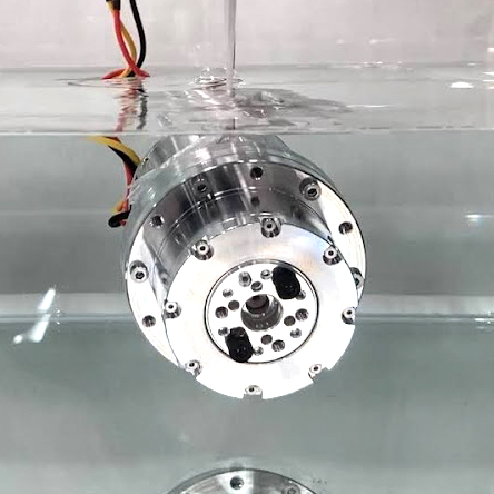
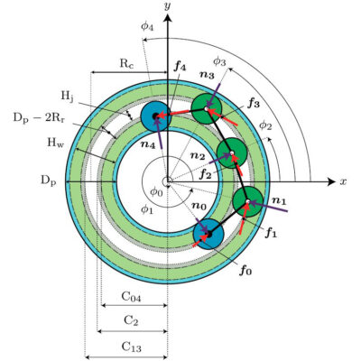
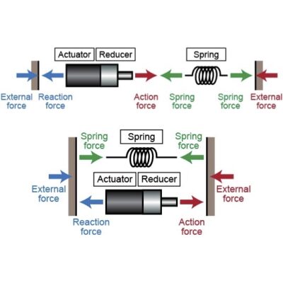
The ideal form of meandering motion of a snake-like robot is already well known. This is called a serpenoid curve, and can be realized by driving the joint angles sinusoidally with respect to time. In this case, the reaction force (force to kick off the ground) received from the ground can be derived using a Coulomb friction model, and the force (joint torque) required for the motion can be obtained. In the research presented here, this dynamic model was also used to investigate how the parallel elastic actuator contributes to the joint torque of the snake-like robot. Of course, the robot’s motion when a specified torque is applied to the joints can also be derived from the calculation. The Coulomb friction model can also be used to calculate the motion of the robot when a specified torque is applied to the joints. However, because the Coulomb friction model does not match reality well, and the friction of the motor reducer can cause errors, it is necessary to check the reliability of the model by comparing experiments and simulations. For this reason, experiments are very important.
Related works
- Atsushi Kakogawa, Taihei Kawabata, and Shugen Ma, Plate-springed Parallel Elastic Actuator for Efficient Snake Robot Movement, IEEE/ASME Transactions on Mechatronics, Vol. 26, Iss. 6, pp. 3051-3063, 2021
- Atsushi Kakogawa, Taihei Kawabata, and Shugen Ma, Plate Springed Parallel Elastic Actuators for Efficient Movement of a Planar Snake Robot, Proceedings of the IEEE/ASME International Conference on Advanced Intelligent Mechatronics (AIM 2019), pp. 235-240, 2019
- 加古川篤,川端泰平,馬書根,並列弾性アクチュエータを用いたヘビ型ロボットの低速運動時におけるエネルギー消費抑制,システム制御情報学会論文誌,32巻,6号,pp. 227-233, 2019
- 加古川篤,馬書根,並列弾性アクチュエータを用いた高効率2次元ヘビ型ロボットの剛性設計,第62回システム制御情報学会研究発表講演会 (SCI’18),2018
- Atsushi Kakogawa, Soo Jeon, and Shugen Ma, Stiffness Design of a Resonance-based Planar Snake Robot with Parallel Elastic Actuators, IEEE Robotics and Automation Letters (RA-L), Vol. 3, Iss. 2, pp. 1284-1291, 2018
Statics of an articulated wheeled in-pipe inspection robot
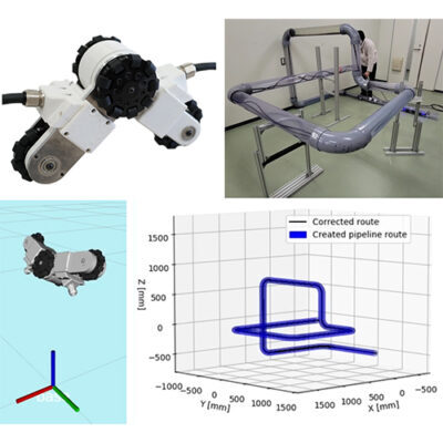
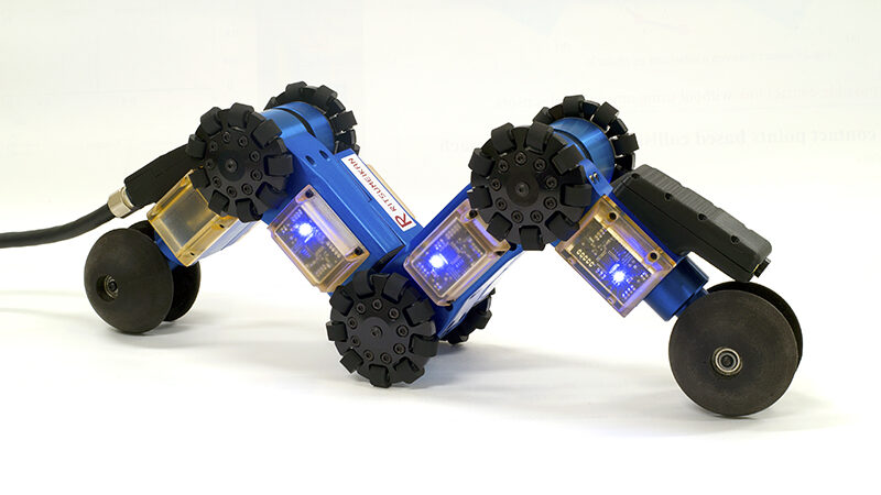
The articulated wheel-type in-pipe inspection robot developed in this laboratory has three joints, which are rotated by the restorative force of a spring or a motor, and the wheels can be propped up against the wall inside the pipe. All three joints are equipped with wheels, each of which can be driven. However, it was not known how the external forces received from the wall would vary depending on parameters such as spring stiffness and natural angle. Therefore, a statics model was developed to derive the relationship between the torque of the joints (by springs and motors) and the external force on the wall for straight and curved pipes, and the design parameters of the springs and the necessary motor torque were calculated to prevent slipping even in the vertical state.
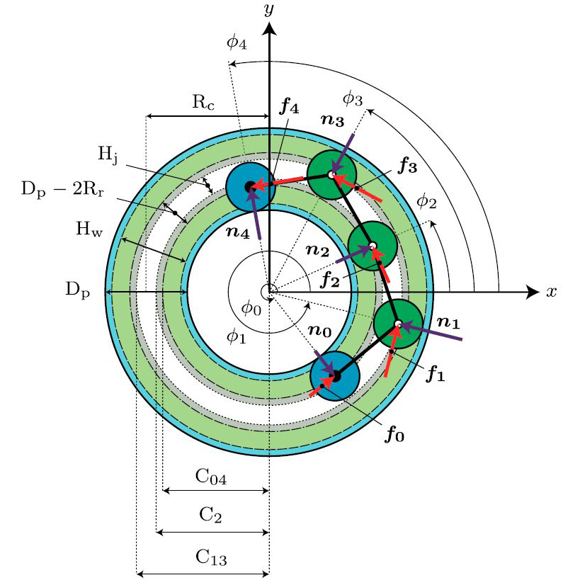
This statics has helped us to understand which of the three joints and three wheels should be driven when the robot pass through a vertical pipe. For example, two of the three joints should be stretched by the strongest possible springs, and two of the three wheels should be driven by the strongest possible motors. At first, we thought that this arrangement of springs and motors would be effective. However, when we analyzed the actual mechanical model, it was found that it is better to distribute the spring torque and motor output to the three joints and place them all in the same position, because the spring torque and motor output can be small. In addition, the torque at the central joint was the most important factor in preventing the wheel from slipping. Therefore, this design method is adopted in the current articulated wheel-type in-pipe inspection robots, in which all joints and wheels generate a thrusting force by means of springs and motors. The torque of the central joint, which is the most important, can be adjusted by a motor.
Related works
- Atsushi Kakogawa, Kenya Murata, and Shugen Ma, Automatic T-branch Travel of an Articulated Wheeled In-pipe Inspection Robot Using Joint Angle Response to Environmental Changes, IEEE Transactions on Industrial Electronics, Vo. 70, Iss. 7, pp. 7041-7050, 2023
- Atsushi Kakogawa and Shugen Ma, Design of a Multilink-articulated Wheeled Pipeline Inspection Robot using Only Passive Elastic Joints, Advanced Robotics (Selected and extended paper from IROS 2016), Vol. 32, Iss. 1, pp. 37-50, 2018
- Atsushi Kakogawa and Shugen Ma, Design of a Multilink-articulated Wheeled Inspection Robot for Winding Pipelines: AIRo-II, Proceedings of the IEEE/RSJ International Conference on Intelligent Robots and Systems (IROS 2016), pp. 2115-2121, 2016

