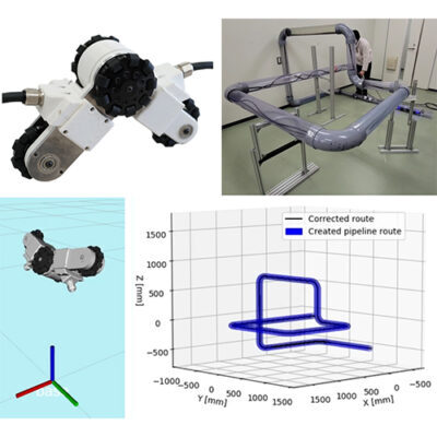
For many years, we have conducted research on robots for inspecting aging pipelines. However, even if damaged or deteriorated sections can be identified with a camera or other sensors, efficient repair or replacement work is difficult if the location of the damaged or deteriorated section is not known. In particular, drawings of pipes laid before and after the period of rapid economic growth often lack information such as route lengths and locations of bends, and in many cases, the drawings themselves do not exist. In this research, we are studying a technology to quantify and visualize the route information of pipeline as the robot moves along the route.
Many methods have been reported to quantify the pipeline path by mounting several types of sensors on an in-pipe robot. However, our target pipe’s inner diameter is less than 4 inches (about 10 cm). This makes it difficult to add multiple sensors to the robot due to space limitations. In this study, we developed a towed sensing unit that can measure the distance traveled and posture of the robot as it is towed by the robot, instead of installing sensors on the robot running in the pipe.
Our towed sensing unit is not equipped with any motor and all wheels are passive. However, the wheels are equipped with encoders to measure the number of rotations, allowing the unit to measure the distance traveled when it is pulled. It is also equipped with a small sensor called an Inertial Measurement Unit (IMU), which contains an acceleration sensor and a gyro sensor, so that the unit’s attitude can also be measured. By sequentially acquiring the travel distance and posture of these towed units, a three-dimensional pipeline route map can be drawn on a computer.
However, even if the above method is actually implemented on a towed unit and pulled by a robot, the obtained pipeline path does not match the actual one. This is because the sensor information contains a certain amount of noise and error. To solve this problem, we devised a route correction technique based on pipe standards. Needless to say, pipes are man-made. The inside diameter and radius of curvature of curved pipes are defined by standards. Using this pre-known information, we can correct the path information so that it is correct even if the towing unit enters a bend, etc., and finally produce a 3D pipeline routing diagram that is close to the real thing.
Related Works
- Chihiro Hirose, Shunsuke Ota, Atsushi Kakogawa, and Shugen Ma, A Pipeline Route Drawing System Equipped with a Towed Unit with Only Low Cost Internal Sensors, IEEE Transactions on Industrial Electronics, Vol. 72, No. 2, pp. 1712-1722, 2025 (Published Online, 2024), https://doi.org/10.1109/TIE.2024.3419240
- Atsushi Kakogawa, Chihiro Hirose, and Shugen Ma, A Standards-Based Pipeline Route Drawing System Using a Towed Sensing Unit, Proceedings of the IEEE/RSJ International Conference on Intelligent Robots and Systems (IROS 2022), pp. 7167-7173, 2022
- 廣瀬千大,加古川篤,馬書根,被牽引式センシングユニットを用いた配管経路作図システム,日本機械学会ロボティクス・メカトロニクス講演会 2022,2P1-M08,2022
- 廣瀬千大,加古川篤,馬書根,配管の長距離経路作図に向けた被牽引センシングシステムの開発,第40回日本ロボット学会学術講演会,3G2-03,2022
- 藤村遼,加古川篤,馬書根,車輪エンコーダとジャイロセンサを搭載した被牽引ユニットによる配管マッピング,日本機械学会ロボティクス・メカトロニクス講演会 2021,2P3-I14,2021

